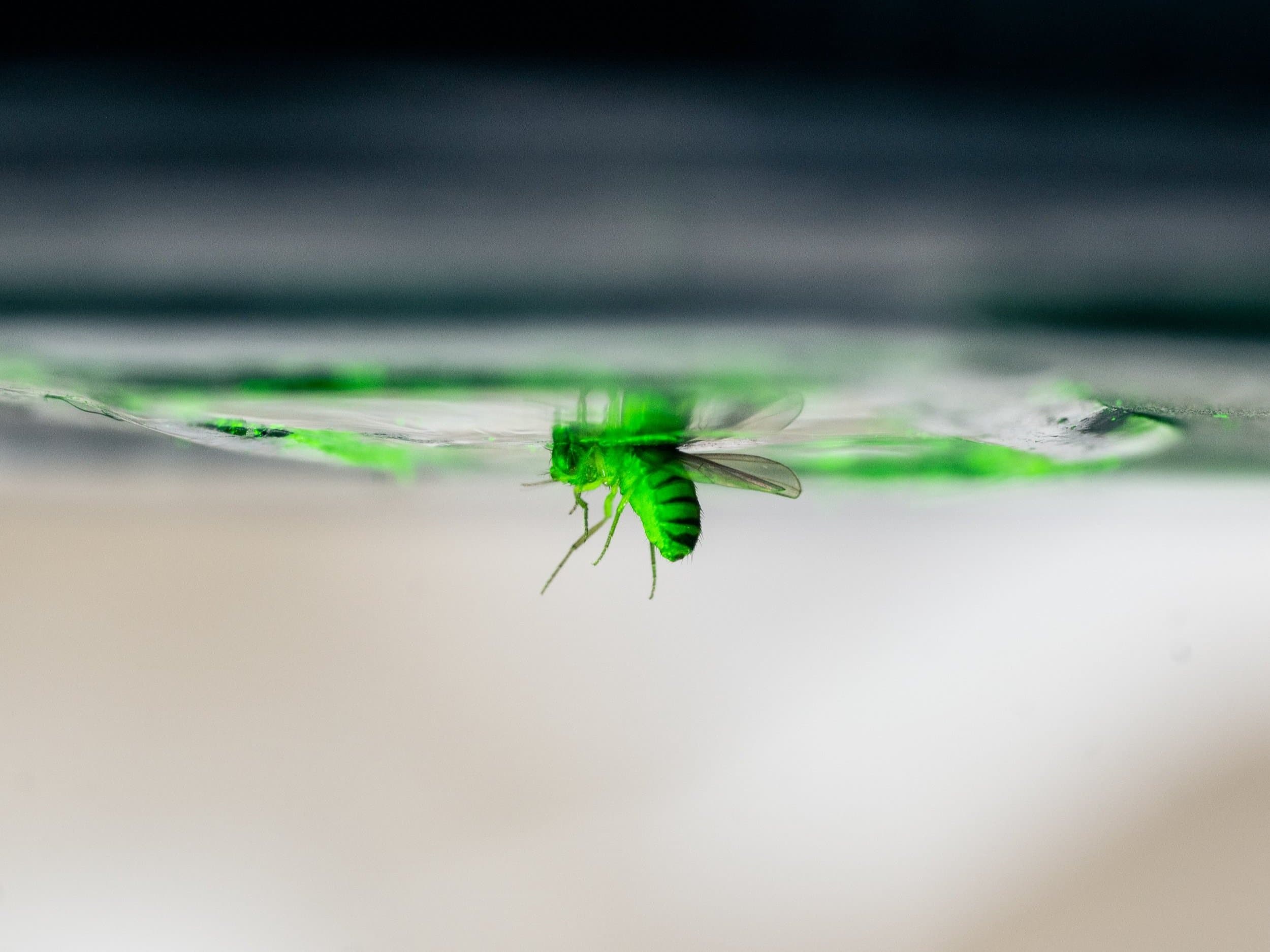
Context
The Behnia Lab, at Columbia's Zuckerman Institute, has about 10 researchers running Drosophila behavior and imaging experiments. When equipment fails and the failure is only discovered mid-experiment, the researchers lose significant time. I joined the lab as Assistant Lab Engineer in August 2026 to work on the hardware behind these experiments.
The Y-Maze Color-Vision Assay
The lab studies color vision in Drosophila. The Y-maze asks a fly to choose between two lights, over and over, and records each choice. Each maze is a Y with three arms: the arm the fly is in stays dark, and the two other arms show the two colors under test, assigned at random. When the fly enters a new arm, that arm goes dark and the colors are redrawn, so every arm entry is one decision and position biases average out.
The rig runs this as a closed loop for up to 8 flies in parallel: camera, tracking, stimulus update, LEDs, many times per second. Stimuli are defined in physical units (photon flux) and converted to LED drive values through a spectrometer calibration, so experiments can be reproduced and compared across days.
240
LED channels, 12-bit PWM
6
LED primaries, UV to orange
8
Flies tracked in parallel
Rebuilding the Rig
The rig had been dismantled and its code lived in a former lab member's personal repository. I took it apart completely, documented every part, then reassembled it, re-mounted the camera, re-installed the layer stack and rewired the microcontroller and power supplies.
Y-maze hardware
- Mazes
- Clear Y-shaped mazes with lids, on a custom PCB with 12 maze footprints
- Stimulus
- An arc of 6 LEDs at the end of each arm, one per primary (UV, violet, blue, green, lime, orange)
- LED drivers
- 10 daisy-chained TLC5947 boards, 240 constant-current channels
- Microcontroller
- Metro M4 Express, receiving stimulus frames from the PC over USB serial
- Backlight
- 850 nm IR LED strips under a paper diffuser: invisible to the flies, so the camera sees each fly as a dark silhouette
- Tracking
- Overhead Basler USB3 camera, background-subtraction tracking in Python and OpenCV
- Power
- Separate 5 V supply for the LEDs (up to 3.6 A), 12 V for the IR strips, USB for the logic
Making It Mobile
The rig used to sit on a fixed desk, run from a desktop PC. I redesigned it to live on wheeled tables: a cage-style frame built on square-profile metal rails, with sliding mounts for the components and the camera mounted on top.
Debugging, Hardware to Software
- Wrote safe test tools for the camera and the microcontroller, including a sweep that lights each of the 240 channels in turn with capped brightness and switches everything off before and after, even on interrupt.
- Located 4 faulty LEDs with a multimeter: two shorted outputs, one damaged LED and one dead channel. The affected mazes are kept dark in software until repaired.
- Fixed a firmware bug that declared 9 driver boards instead of 10, which made the last maze light up as a copy of the first board.
- Settled the hardware facts the old documents disagreed on: the number of driver boards, the power distribution and the full channel map.
Code and Documentation
I moved the inherited Python codebase into the lab GitLab, with protected branches and a reproducible conda environment, archived the existing sessions, and fixed Windows incompatibilities so the rig can later run from a portable laptop. I also reconstructed the rig's history from git and the lab notes into a technical reference for anyone who has to run, debug or extend it.
Startup Self-Checks
The second part of the work addresses the failure mode itself. I built self-check routines that run when a rig starts up, so researchers detect hardware anomalies at launch instead of after a lost session.
Self-check deployments
- LED mixers
- Hardware and software: NI-DAQ, resistor and photodetector circuit, Python, Streamlit. Deployed on 4 to 6 rigs.
- Olfactometer
- Software: Python, Streamlit. Deployed on 1 rig.
Cover photo: Behnia Lab website.